5069-IF8: Wiring, Configuration, Scaling, and Diagnostics
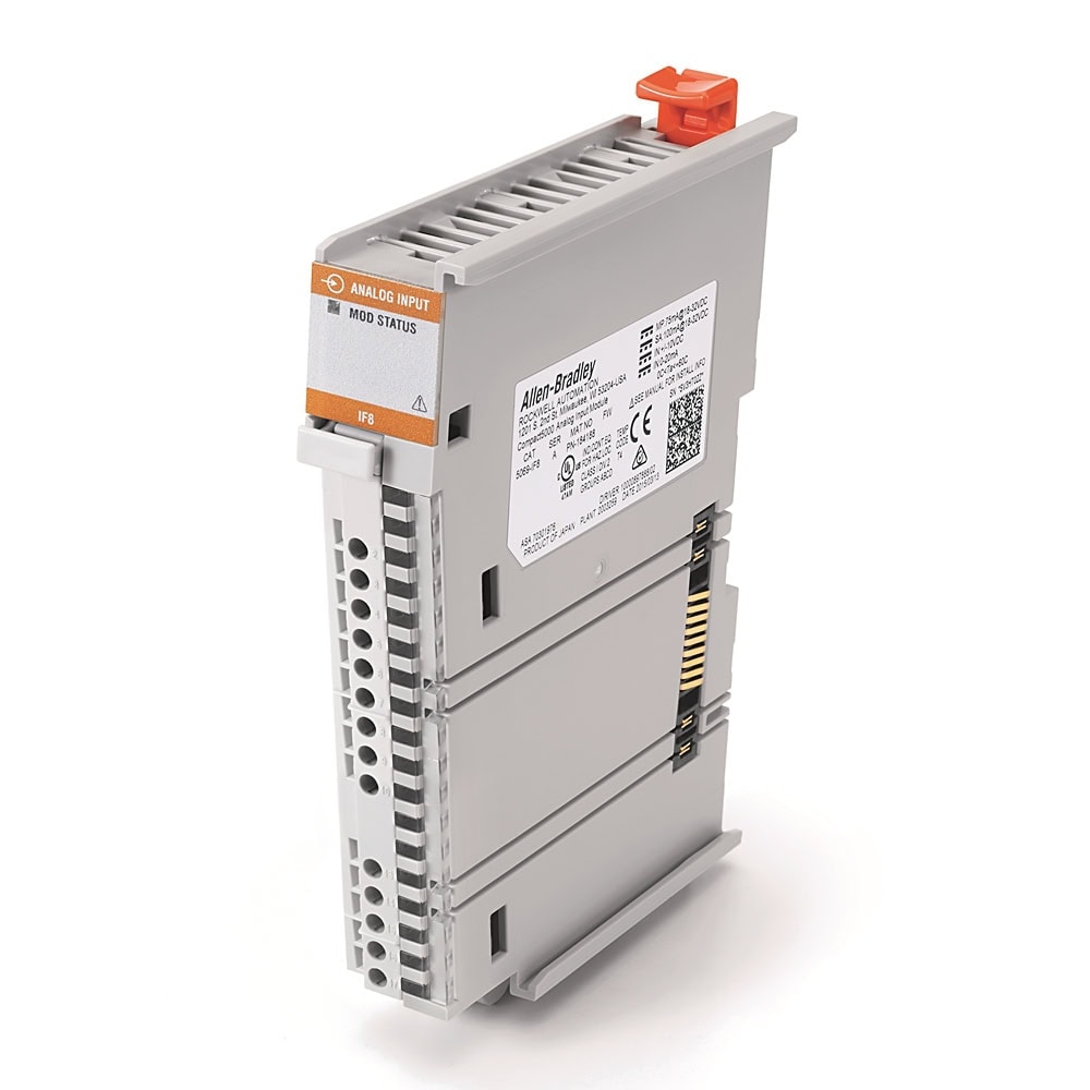 5069-IF8 8-channel analog input module">
1. Module Overview
The 5069-IF8 belongs to Rockwell Automation's Compact 5000 I/O family, designed for the CompactLogix 5380, Compact GuardLogix 5380, and CompactLogix 5480 controllers. It provides 8 non-isolated analog input channels (Series A: differential, Series B: single-ended) with per-channel signal type selection, 16-bit resolution, and built-in open-wire detection. The module reports data in IEEE 754 floating-point format (REAL data type) in signal-level engineering units.
Catalog Number Breakdown
| Code | Meaning | Value |
|---|---|---|
| 5069 | Platform | Compact 5000 — high-speed backplane I/O bus |
| I | Direction | Input module |
| F | Signal type | Flexible — voltage or current (per channel) |
| 8 | Channel count | 8 channels (differential or single-ended depending on series) |
Key Specifications
| Parameter | Value |
|---|---|
| Input Channels | Series A: 8 differential | Series B: 8 single-ended |
| Signal Types (per channel) | Voltage: 0–5V, 0–10V, ±10V | Current: 0–20mA, 4–20mA |
| Resolution | 16-bit (65,536 counts full-scale) |
| Accuracy | ±0.1% of full scale at 25°C |
| Input Impedance | Voltage: >1 MΩ | Current: 90Ω typical (70–110Ω range) |
| Scan Time | 625 µs per channel. Per group (Ch 0–3 or Ch 4–7): 2.5 ms. Actual rate depends on notch filter setting. |
| Notch Filter | Configurable: 5, 10, 15, 20, 50, 60 Hz (default), 100, 200, 500, 1000, 2500, 5000, 10000, 15625, 25000, 31250, 62500 Hz |
| Open-Wire Detection | Supported on both voltage and current modes. Voltage: detects when signal reaches full-scale. Current: detects when signal drops below 100 µA. |
| Isolation | 250V continuous (Basic Insulation), 50V Functional Isolation between SA power and input ports. No isolation between individual input ports. |
| Terminal Block | 5069-RTB18-SPRING or 5069-RTB18-SCREW RTB (18-pin), 22–16 AWG |
| Power Consumption | 2.1W max (voltage mode), 2.4W max (current mode). MOD power: 75mA @ 18–32V DC. SA power: 100mA @ 18–32V DC. |
2. Hardware Installation
The 5069-IF8 mounts on standard 35mm DIN rail and connects to the Compact 5000 system bus via the side-mount connector. No backplane is required.
System Assembly Order
Left to right, the physical assembly must follow this order:
- CompactLogix 5380 Controller (e.g., 5069-L306ER, 5069-L310ER, 5069-L320ER) or Compact 5000 EtherNet/IP Adapter (5069-AENTR) — leftmost device
- Compact 5000 I/O Modules — installed to the right of the controller or adapter. The 5069-IF8 can occupy any available slot
- End Cap — required on the last module in the system to cover the exposed bus interconnection. The end cap ships with the controller.
Mounting Procedure
- Ensure all power is removed from the system before installing modules
- Hook the top clip of the 5069-IF8 onto the DIN rail
- Pivot the module downward and press the bottom clip until it snaps into place
- Slide the module to the left until the side-bus connector seats firmly into the adjacent module — you will hear or feel a click
- Confirm the bus connector latch is fully engaged (visible through the side window)
- Install the removable terminal block (RTB) onto the front of the module — it snaps into the two retention clips
3. Wiring
The 5069-IF8 uses an 18-pin removable terminal block (RTB). Each channel has dedicated signal (+) and signal (−) terminals. Two shared shield/drain terminals are at the bottom of the terminal block (pins 16 and 17). The wiring differs depending on whether the channel is configured for voltage or current input.
Terminal Block Pinout — All 8 Channels
| Channel | Signal + (IN+) | Signal − (IN−) | Voltage Wiring | Current Wiring |
|---|---|---|---|---|
| Ch 0 | Pin 0 | Pin 1 | V+ to Pin 0, V− to Pin 1 | Loop+ to Pin 0, Loop− to Pin 1 |
| Ch 1 | Pin 2 | Pin 3 | V+ to Pin 2, V− to Pin 3 | Loop+ to Pin 2, Loop− to Pin 3 |
| Ch 2 | Pin 4 | Pin 5 | V+ to Pin 4, V− to Pin 5 | Loop+ to Pin 4, Loop− to Pin 5 |
| Ch 3 | Pin 6 | Pin 7 | V+ to Pin 6, V− to Pin 7 | Loop+ to Pin 6, Loop− to Pin 7 |
| Ch 4 | Pin 8 | Pin 9 | V+ to Pin 8, V− to Pin 9 | Loop+ to Pin 8, Loop− to Pin 9 |
| Ch 5 | Pin 10 | Pin 11 | V+ to Pin 10, V− to Pin 11 | Loop+ to Pin 10, Loop− to Pin 11 |
| Ch 6 | Pin 12 | Pin 13 | V+ to Pin 12, V− to Pin 13 | Loop+ to Pin 12, Loop− to Pin 13 |
| Ch 7 | Pin 14 | Pin 15 | V+ to Pin 14, V− to Pin 15 | Loop+ to Pin 14, Loop− to Pin 15 |
| Shield | Pin 16, Pin 17 | Connect cable shield/drain wire to Pin 16 or Pin 17 (shared across all channels). Ground two devices maximum. | ||
2-Wire Loop-Powered Transmitter (4–20mA)
A 2-wire (loop-powered) transmitter is the most common analog field device in process control. The transmitter draws its operating power from the 4–20mA current loop itself — no separate power supply connection is needed at the transmitter. Wiring order:
- 24VDC power supply (+) connects to the transmitter's positive terminal
- Transmitter negative terminal connects to the module's IN+ pin for that channel
- Module IN− pin connects back to the 24VDC power supply (−), completing the loop
- Connect the cable shield/drain wire to the module's Shield terminal (Pin 16 or 17) — ground at the module end only
4-Wire Externally-Powered Transmitter (4–20mA)
A 4-wire transmitter has its own dedicated power supply (typically 24VDC) and outputs a 4–20mA signal on separate terminals. Wiring is simpler:
- Power the transmitter from a separate 24VDC supply (+ and − to the transmitter's power terminals)
- Connect the transmitter's signal output (+) to the module's IN+ pin
- Connect the transmitter's signal output (−) to the module's IN− pin
- Connect the cable shield/drain wire to the module's Shield terminal (Pin 16 or 17)
Voltage Input Wiring (0–5V, 0–10V, or ±10V)
- Connect the sensor or signal source's voltage output (+) to the module's IN+ pin
- Connect the sensor or signal source's voltage output (−) or common to the module's IN− pin
- Connect the cable shield/drain wire to the module's Shield terminal (Pin 16 or 17)
Shielded Cable and Grounding Best Practices
- Always use shielded, twisted-pair cable for analog signals.
- Ground the shield at one end only (the module end) to prevent ground loops. Use the module's shield/drain terminal.
- Route analog cables in separate conduit or cable tray from power wiring (480V, VFD output cables).
- Maintain a minimum 12-inch (300mm) separation from power cables when parallel runs are unavoidable.
- Cross power cables at 90-degree angles when analog and power paths must intersect.
- Keep cable runs as short as practical — longer runs increase noise susceptibility.
- For current loops: 4–20mA signals are inherently more noise-immune than voltage signals over long distances. Prefer current loops for runs over 50 feet (15m).
4. Studio 5000 Configuration
Adding the 5069-IF8 to the I/O Tree
- In Studio 5000 Logix Designer, expand I/O Configuration in the Controller Organizer (left panel)
- Right-click the controller node → New Module
- In the module catalog, search for
5069-IF8→ select it → click Create - Set the Slot Number to match the physical position of the module in the Compact 5000 assembly (Slot 0 = first module right of the controller)
- Give the module a descriptive name (e.g.,
Analog_Inputs_1) - Click OK to add the module. It appears in the I/O tree under the controller
Per-Channel Configuration
Double-click the 5069-IF8 module in the I/O tree to open its properties. Navigate to the Ch# Configuration tabs (one tab per channel). Each channel has the following settings:
| Setting | Options | Notes |
|---|---|---|
| Enable | Enabled / Disabled | Disabled channels are ignored. Disable unused channels to reduce scan overhead. |
| Signal Type | Voltage / Current | Must match the physical wiring for that channel. |
| Range | Voltage: 0–5V, 0–10V, ±10V | Current: 0–20mA, 4–20mA | Available ranges depend on signal type selection. Range must match the transmitter output. |
| Notch Filter | 5, 10, 15, 20, 50, 60 (default), 100, 200, 500, 1000, 2500, 5000, 10000, 15625, 25000, 31250, 62500 Hz | Use 50 Hz or 60 Hz to reject power line noise. Lower frequencies provide better noise rejection but slower sample rates. Higher frequencies allow faster sampling. |
| Digital Filter | 0 ms (disabled) to 32,767 ms | First-order lag filter time constant per channel. Smooths input data noise transients. A value of 0 disables the filter. |
| High Alarm | Enable / Disable, Setpoint | Module sets an alarm bit in the input tag when the raw value exceeds the setpoint. |
| Low Alarm | Enable / Disable, Setpoint | Module sets an alarm bit when the raw value falls below the setpoint. |
| Open-Wire Detection | Enable / Disable | Available in both voltage and current modes. Current mode: signal drops below 100 µA. Voltage mode: signal reaches full-scale of the input range. |
Data Format — Floating-Point Engineering Units
The 5069-IF8 reports analog values as REAL (IEEE 754, 32-bit floating point) in scaled engineering units. Unlike older 1769 analog modules that report raw integer counts, the 5069-IF8 Chxx.Data tag already contains the value in signal units (volts or milliamps). No raw-to-engineering-unit conversion is required at the module level.
| Signal Range | Chxx.Data Minimum | Chxx.Data Maximum | Units |
|---|---|---|---|
| 0–5V | 0.0 | 5.0 | Volts |
| 0–10V | 0.0 | 10.0 | Volts |
| ±10V | −10.0 | 10.0 | Volts |
| 0–20mA | 0.0 | 20.0 | mA |
| 4–20mA | 4.0 | 20.0 | mA |
Built-In Scaling to Engineering Units
The 5069-IF8 module properties include built-in Scaling that converts the signal-level value to process engineering units directly in the module. When configured, the I.Chxx.Data tag (REAL data type) contains the pre-scaled value in your chosen engineering units (e.g., PSI, degrees, percent). Configure the High and Low Engineering values and the corresponding High and Low Signal values on the Scaling tab of each channel’s configuration page in Studio 5000. This eliminates the need for SCP instructions in ladder logic for basic linear scaling.
Alarm Configuration
Each channel supports High and Low alarm setpoints configured in the module properties. When a channel value exceeds the high setpoint or drops below the low setpoint, the module sets the corresponding alarm bit in the input tag structure:
Local:X:I.ChXHAlarm— set when input exceeds the high setpointLocal:X:I.ChXLAlarm— set when input drops below the low setpoint
These bits can be used directly in ladder logic to trigger warnings or shutdowns without requiring separate comparison instructions.
5. Reading Analog Values in Ladder Logic
Input Tag Structure
When the 5069-IF8 is added to the I/O tree in slot 3 (for example), Studio 5000 creates the following tags automatically. Channel tags use two-digit numbering (Ch00–Ch07):
| Tag | Data Type | Description |
|---|---|---|
Local:3:I.Ch00.Data | REAL | Channel 0 data in scaled engineering units |
Local:3:I.Ch01.Data | REAL | Channel 1 data in scaled engineering units |
Local:3:I.Ch02.Data | REAL | Channel 2 data in scaled engineering units |
Local:3:I.Ch03.Data | REAL | Channel 3 data in scaled engineering units |
Local:3:I.Ch04.Data | REAL | Channel 4 data in scaled engineering units |
Local:3:I.Ch05.Data | REAL | Channel 5 data in scaled engineering units |
Local:3:I.Ch06.Data | REAL | Channel 6 data in scaled engineering units |
Local:3:I.Ch07.Data | REAL | Channel 7 data in scaled engineering units |
Local:3:I.Ch00.HAlarm | BOOL | Channel 0 high alarm active |
Local:3:I.Ch00.LAlarm | BOOL | Channel 0 low alarm active |
Local:3:I.Ch00.OpenWire | BOOL | Channel 0 open-wire detection (voltage: signal reaches full-scale; current: signal drops below 100µA) |
Local:3:I.Ch00.Underrange | BOOL | Channel 0 under-range flag |
Local:3:I.Ch00.Overrange | BOOL | Channel 0 over-range flag |
The same tag pattern applies to all 8 channels (Ch00 through Ch07). Replace 3 with your actual slot number.
Scaling with SCP (Scale with Parameters)
Since the 5069-IF8 Chxx.Data tag already contains a REAL value in signal units (e.g., milliamps or volts), the SCP instruction converts signal-level values to process engineering units. It performs a linear interpolation between the signal range and the desired engineering range. Alternatively, you can configure the module’s built-in Scaling feature to do this conversion automatically (see above). If you use module-level scaling, no SCP is needed.
| SCP Parameter | Description | Example Value (4–20mA → 0–100 PSI) |
|---|---|---|
| Input | Channel data in signal units | Local:3:I.Ch00.Data (REAL, in mA) |
| Input Min | Signal value at engineering zero | 4.0 (4 mA) |
| Input Max | Signal value at engineering full scale | 20.0 (20 mA) |
| Output Min | Engineering value at minimum signal | 0.0 (0 PSI) |
| Output Max | Engineering value at maximum signal | 100.0 (100 PSI) |
| Output | Destination tag for scaled value | Pressure_PSI (REAL) |
Practical Example: 4–20mA Pressure Transmitter, 0–100 PSI
Scenario: A pressure transmitter is wired to Channel 0 (slot 3), configured for 4–20mA. The transmitter outputs 4mA at 0 PSI and 20mA at 100 PSI. The goal is to read the pressure in engineering units and trigger an alarm at 85 PSI.
Output = ((Input - InMin) / (InMax - InMin)) * (OutMax - OutMin) + OutMin. If you configure Scaling in the module properties, the Chxx.Data tag already contains the process value in engineering units, and no SCP is needed.
Using Comparison Instructions for Alarm Logic
In ladder diagram format, use these comparison instructions against the scaled engineering value:
| Instruction | Use Case | Example |
|---|---|---|
| GRT (Greater Than) | High alarm | GRT Pressure_PSI 85.0 → energize alarm output |
| LES (Less Than) | Low alarm | LES Pressure_PSI 5.0 → energize low-pressure warning |
| GEQ (Greater Than or Equal) | High-high shutdown | GEQ Pressure_PSI 95.0 → emergency shutdown |
| LEQ (Less Than or Equal) | Low-low shutdown | LEQ Pressure_PSI 2.0 → pump dry-run protection |
6. Calibration & Accuracy
Understanding 16-Bit Resolution
The 5069-IF8 provides 16-bit resolution using a Sigma-Delta, two 24-bit multiplexed ADC. Although the module reports values as REAL (floating point) in engineering units, the underlying conversion provides approximately 65,536 discrete levels across the full input range. For a 4–20mA signal representing 0–100 PSI:
| Metric | Value |
|---|---|
| ADC resolution | 16 bits (65,536 levels across full scale) |
| Current resolution (0–21 mA range) | <0.32 µA/count |
| Module accuracy (±0.1% full scale at 25°C) | ±0.1 PSI on a 100 PSI range |
| Accuracy drift with temperature | ±0.30% of full scale over 0–60°C |
| Effective measurement precision | Typically limited by the transmitter, not the module |
Digital Noise Filtering
The configurable digital filter in the module properties attenuates noise at the selected frequency. Guidelines for filter selection:
| Filter Setting | Best For | Tradeoff |
|---|---|---|
| 5–10 Hz | Slow process variables (level, temperature) | Best noise rejection but slowest sample rate (215+ ms minimum RPI) |
| 50 Hz / 60 Hz (default) | General process signals in 50Hz or 60Hz power environments | Good balance of noise rejection and response time (~20 ms minimum RPI per channel) |
| 500–1000 Hz | Moderate-speed signals (flow, some pressure applications) | Less filtering, faster response (2–5 ms minimum RPI) |
| 10,000–62,500 Hz | High-speed signals requiring minimal latency | Minimal noise rejection, fastest possible sample rates (<1 ms) |
Software Averaging in Ladder Logic
For additional smoothing beyond the module's digital filter, implement a rolling average in the PLC program. A simple first-order exponential filter (also called a moving average or lag filter):
Sensor Calibration Procedure
- Verify the module configuration — confirm the correct signal type and range are set in Studio 5000 for the channel under test
- Apply a known zero signal — for a 4–20mA transmitter, disconnect the transmitter and inject exactly 4.000mA using a calibrated loop calibrator (e.g., Fluke 789). Record the
Chxx.Datavalue displayed in the PLC (should read approximately 4.0 mA, or the corresponding scaled engineering value). - Apply a known full-scale signal — inject exactly 20.000mA. Record the
Chxx.Datavalue. - Verify linearity — inject a mid-range signal (12.000mA = 50% of range). Confirm the value reads within acceptable tolerance of the expected value.
- Adjust scaling if needed — if the zero or span readings are slightly off, use the module’s Sensor Offset feature (
O.Chxx.SensorOffsettag) to compensate, or adjust the SCP Input Min/Max to match actual observed values rather than the theoretical 4.0 and 20.0. - Document the calibration — record date, calibrator serial number, as-found and as-left values for traceability.
7. Diagnostics & Troubleshooting
LED Indicators
| LED | State | Meaning |
|---|---|---|
| MOD (Module Status) | Solid green | Module operating normally |
| MOD | Flashing green | Module is powered but not configured (no controller connection) |
| MOD | Solid red | Unrecoverable fault — replace module |
| MOD | Flashing red | Recoverable fault — check configuration, reset |
| I/O | Solid green | Active connection to controller, data exchanging |
| I/O | Flashing green | No active connection — module not owned by a controller |
| I/O | Solid red | Connection faulted — check I/O tree configuration |
| Ch 0–7 LEDs | Solid green | Channel enabled and reading within range |
| Ch 0–7 LEDs | Red | Channel fault: open wire, over-range, or under-range |
| Ch 0–7 LEDs | Off | Channel disabled in configuration |
Diagnostic Tags in the Controller
The module populates diagnostic bits in the input tag structure for each channel:
| Tag | Condition | Action |
|---|---|---|
Local:X:I.Chxx.Overrange | Input signal exceeds configured range maximum | Check transmitter output; verify range setting matches actual signal |
Local:X:I.Chxx.Underrange | Input signal below configured range minimum | Check for broken wire, transmitter power, or incorrect range |
Local:X:I.Chxx.OpenWire | Open wire detected (voltage: signal reaches full-scale; current: signal drops below 100µA) | Inspect wiring continuity; check transmitter power supply; verify terminal connections |
Local:X:I.Chxx.Fault | General channel fault — data quality is bad | Check channel LED; review module diagnostics in Studio 5000 |
Local:X:I.Chxx.OverTemperature | Module is above rated operating temperature limits | Check ambient temperature; verify mounting clearances; reduce power dissipation |
Local:X:I.Chxx.FieldPowerOff | Field power not present on the channel | Verify SA power bus is established and powered |
Local:X:I.Chxx.Uncertain | Channel data may be imperfect — degree of inaccuracy unknown | Troubleshoot the module to identify the source of inaccuracy |
Local:X:I.Chxx.NotANumber | Most recently received data value was not a valid number | Check channel configuration; verify signal is within valid range |
Local:X:I.Chxx.CalFault | Calibration fault on the channel | Re-calibrate the channel or reset the module; replace if persistent |
Local:X:I.Chxx.Calibrating | Channel calibration is in progress | Wait for calibration to complete — do not rely on data while this is set |
Local:X:I.Chxx.LLAlarm | Low-Low process alarm is active | Signal is below the configured LLAlarmLimit threshold |
Local:X:I.Chxx.LAlarm | Low process alarm is active | Signal is below the configured LAlarmLimit threshold |
Local:X:I.Chxx.HAlarm | High process alarm is active | Signal is above the configured HAlarmLimit threshold |
Local:X:I.Chxx.HHAlarm | High-High process alarm is active | Signal is above the configured HHAlarmLimit threshold |
Local:X:I.Chxx.RateAlarm | Rate of change alarm is active | Signal is changing faster than the configured RateAlarmLimit |
Local:X:I.Chxx.Data | Channel data in scaled engineering units (REAL) | Primary data tag — use this for process value reads |
Local:X:I.Chxx.RollingTimestamp | 15-bit ms timer recorded at last scan (INT) | Use to calculate time between samples |
Per-Channel Output Control Tags (write to these to enable/unlatch alarms)
| Tag | Condition | Action |
|---|---|---|
Local:X:O.Chxx.LLAlarmEn | Write 1 to enable the Low-Low process alarm | Must be enabled for the I.Chxx.LLAlarm tag to activate |
Local:X:O.Chxx.LAlarmEn | Write 1 to enable the Low process alarm | Must be enabled for the I.Chxx.LAlarm tag to activate |
Local:X:O.Chxx.HAlarmEn | Write 1 to enable the High process alarm | Must be enabled for the I.Chxx.HAlarm tag to activate |
Local:X:O.Chxx.HHAlarmEn | Write 1 to enable the High-High process alarm | Must be enabled for the I.Chxx.HHAlarm tag to activate |
Local:X:O.Chxx.RateAlarmEn | Write 1 to enable the Rate of change alarm | Must be enabled for the I.Chxx.RateAlarm tag to activate |
Local:X:O.Chxx.LLAlarmUnlatch | Write 1 to unlatch the Low-Low alarm | Only needed if alarm latching is enabled in configuration |
Local:X:O.Chxx.LAlarmUnlatch | Write 1 to unlatch the Low alarm | Only needed if alarm latching is enabled |
Local:X:O.Chxx.HAlarmUnlatch | Write 1 to unlatch the High alarm | Only needed if alarm latching is enabled |
Local:X:O.Chxx.HHAlarmUnlatch | Write 1 to unlatch the High-High alarm | Only needed if alarm latching is enabled |
Local:X:O.Chxx.RateAlarmUnlatch | Write 1 to unlatch the Rate alarm | Only needed if alarm latching is enabled |
Local:X:O.Chxx.SensorOffset | Write a REAL value to apply a sensor offset calibration | Used for field calibration — offsets the raw reading by this value |
Common Troubleshooting Scenarios
| Symptom | Likely Cause | Resolution |
|---|---|---|
| Raw value reads 0 on a 4–20mA channel | No current flowing — broken wire, transmitter not powered, or channel configured as voltage instead of current | Verify wiring continuity with a multimeter. Confirm channel is configured for current mode. Check the 24VDC loop power supply. |
| Raw value reads −32,768 or 32,767 (pegged) | Signal out of range — wrong range selected, or sensor is outputting beyond the configured scale | Measure the actual signal with a multimeter. Match the module range to the transmitter's output range. |
| Reading fluctuates or oscillates | Electrical noise, ground loop, or unshielded cable | Verify shielded cable is used. Ground shield at one end only. Increase digital filter (50/60 Hz). Separate analog cables from power wiring. |
| Reading has a consistent offset | Ground loop, sensor calibration drift, or incorrect SCP scaling | Inject a known signal with a loop calibrator. If module reads correctly but sensor does not, recalibrate the sensor. If module reads incorrectly, check for ground loops. |
| Open-wire alarm on a working channel | Intermittent connection, loose terminal, or cable damage | Reseat the terminal block. Inspect wire terminations. Wiggle-test the cable at the terminal while monitoring the tag. |
| Module shows yellow triangle in I/O tree | Module not present, wrong slot assignment, or firmware mismatch | Verify slot number in Studio 5000 matches physical position. Check module is fully seated on the DIN rail and bus connector is latched. |
| All channels read same erratic value | Module-level fault, bus connector issue, or power supply problem | Reseat module on DIN rail. Check bus connector engagement. Try swapping with a known-good module. |
8. Related 5069 Analog Input Modules
The Compact 5000 platform includes several analog input modules for different channel counts and signal types. Select based on your application requirements:
| Catalog Number | Channels | Signal Type | Key Feature |
|---|---|---|---|
| 5069-IF4IH | 4 (isolated) | Voltage / Current / HART | 4-channel isolated current/voltage/HART input module. Supports HART pass-through for smart transmitter configuration and diagnostics. |
| 5069-IF8 | 8 (non-isolated) | Voltage / Current (per channel) | This module. The most common general-purpose analog input for the platform. |
| 5069-IY4 / 5069-IY4K | 4 | Voltage / Current / RTD / Thermocouple | Multi-mode input supporting current, voltage, RTD, thermocouple, and millivolt signals on each channel. The “K” variant is conformal-coated for harsh environments. |
9. Related Guides & Resources
| Resource | Description |
|---|---|
| 5069-OF8 Analog Output Guide | Configuration and wiring for the 8-channel Compact 5000 analog output module — companion to this input guide. |
| 5069 Digital Input Guide | Setup guide for 5069-IB16 and related digital input modules in the Compact 5000 platform. |
| CompactLogix 5069-L306ER Setup Guide | First-time controller setup, power wiring, Studio 5000 project creation, and basic ladder logic for the Compact 5000 platform. |
| PLC Sensor Calibration & Scaling (Blog) | In-depth tutorial on analog sensor scaling with worked examples for pressure, temperature, and flow applications. |
Reference Documentation
The following Rockwell Automation publications were used as references for this guide. These are the official manufacturer documents for the hardware covered in this article.
| Publication | Description | Download |
|---|---|---|
| 5069-UM005 | Compact 5000 Analog I/O Modules User Manual | |
| 5069-IN010 | 5069-IF8 Installation Instructions | |
| 5069-TD001 | Compact 5000 I/O Technical Data |
Shop the Compact 5000 I/O Range
Analog input and output modules plus the full Compact 5000 I/O catalog.