5069-IB16: Installation, Wiring, Configuration, and Programming Guide
 5069-IB16 16-channel 24VDC digital input module">
1. Module Overview
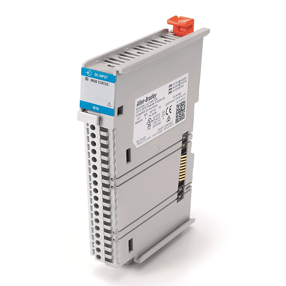
The 5069-IB16 is a fixed 16-point sink-type digital input module designed for the Compact 5000 I/O platform. It reads 24VDC discrete signals from field devices and presents them to the CompactLogix 5380 controller as a 16-bit input data word. Each channel has individual LED indicators and configurable input filter times for noise rejection.
Catalog Number Breakdown
| Code | Meaning | Value |
|---|---|---|
| 5069 | Platform | Compact 5000 -- high-speed local I/O bus |
| I | Module type | Input |
| B | Signal type | DC (B = DC digital; V = AC/DC isolated) |
| 16 | Channel count | 16 discrete input points |
Key Specifications
| Parameter | Value |
|---|---|
| Number of Inputs | 16 |
| Rated Voltage | 24VDC (range: 10 -- 32VDC) |
| Input Type | Sink (current flows into common terminal) |
| ON-State Voltage | 10VDC minimum (guaranteed ON above 10V) |
| OFF-State Voltage | 5VDC maximum (guaranteed OFF below 5V) |
| Input Current (ON) | Approximately 6 mA per channel at 24VDC (range: 4 -- 7.4 mA at 10 -- 32VDC) |
| Input Filter Time | User-selectable: 0 -- 50 ms (hardware delay: 50 us + filter time) |
| Isolation | Channels share a common reference (non-isolated) |
| Terminal Block Type | Removable 18-position RTB (5069-RTB18-SPRING or 5069-RTB18-SCREW, ordered separately) |
| Wire Gauge | 22 -- 16 AWG (0.34 -- 1.5 mm²) solid or stranded shielded copper wire |
| Power Dissipation (max) | 3.9 W |
| MOD Power | 75 mA @ 18 -- 32VDC |
| SA Power | 200 mA @ 10 -- 32VDC |
| Operating Temperature | 0 to 60 C (32 to 140 F) |
2. Hardware Installation
The 5069-IB16 mounts on a standard 35mm DIN rail as part of the Compact 5000 system assembly. Modules connect laterally via the high-speed I/O bus -- there is no separate backplane.
System Assembly Order
Left to right, the mandatory assembly order is:
| Position | Module | Example |
|---|---|---|
| 1 (leftmost) | Power Supply | 5069-PA2 (120/240VAC) or 5069-PD1 (24VDC) |
| 2 | Controller | 5069-L306ER, 5069-L310ER, 5069-L320ER, etc. |
| 3 -- 18 | I/O Modules | 5069-IB16 in any available slot (up to 16 local modules) |
Installation Steps
- Power off the system. Disconnect all power sources to the Compact 5000 assembly before adding or removing modules.
- Mount the DIN rail. Secure a 35mm DIN rail in the panel with appropriate spacing (minimum 120mm clearance above and below for airflow).
- Snap the module onto the DIN rail. Hook the top rail clip over the DIN rail, then press the bottom of the module until the lower clip locks into place with an audible click.
- Slide the module against the adjacent module (controller or previous I/O module) until the I/O bus connector engages. You will feel it seat firmly. The bus connector is keyed -- it only goes one way.
- Verify the module is fully seated. There should be no visible gap between adjacent modules. An incomplete bus connection causes module faults.
- Note the slot number. Count from left to right starting at the first I/O module position after the controller. The first module is Slot 1, the second is Slot 2, and so on. Record the slot number for Studio 5000 configuration.
Terminal Block Removal
The 5069-IB16 uses a removable 18-position terminal block (RTB), either the 5069-RTB18-SPRING (spring-clamp) or 5069-RTB18-SCREW (screw-type). RTBs must be ordered separately -- they do not ship with the module. This allows you to pre-wire the terminal block at a bench before snapping it onto the module, or to swap a module without rewiring:
- Pull the orange release latch at the top of the terminal block outward.
- Slide the terminal block straight off the module face.
- To reinstall, align the terminal block with the module pins and press firmly until the latch clicks closed.
3. Wiring
Terminal Assignments
The 5069-IB16 uses an 18-position removable terminal block (5069-RTB18-SPRING or 5069-RTB18-SCREW, ordered separately). The 16 input channels occupy pins 0 through 15. Pins 16 and 17 are not connected. The common return path is through the internal module circuitry to the SA(-) terminal on the SA power bus RTB -- there are no dedicated COM pins on the field wiring RTB.
| Pin | Function | Tag Address (Slot 1) |
|---|---|---|
| 0 | Input 0 | Local:1:I.Pt00.Data |
| 1 | Input 1 | Local:1:I.Pt01.Data |
| 2 | Input 2 | Local:1:I.Pt02.Data |
| 3 | Input 3 | Local:1:I.Pt03.Data |
| 4 | Input 4 | Local:1:I.Pt04.Data |
| 5 | Input 5 | Local:1:I.Pt05.Data |
| 6 | Input 6 | Local:1:I.Pt06.Data |
| 7 | Input 7 | Local:1:I.Pt07.Data |
| 8 | Input 8 | Local:1:I.Pt08.Data |
| 9 | Input 9 | Local:1:I.Pt09.Data |
| 10 | Input 10 | Local:1:I.Pt01.Data0 |
| 11 | Input 11 | Local:1:I.Pt01.Data1 |
| 12 | Input 12 | Local:1:I.Pt01.Data2 |
| 13 | Input 13 | Local:1:I.Pt01.Data3 |
| 14 | Input 14 | Local:1:I.Pt01.Data4 |
| 15 | Input 15 | Local:1:I.Pt01.Data5 |
| 16 | No Connect | -- |
| 17 | No Connect | -- |
Sink Wiring Configuration
For sink wiring (the standard configuration for the 5069-IB16), connect field devices as follows:
| From | To | Description |
|---|---|---|
| +24VDC supply | Field device (one side) | Positive leg of field power supply |
| Field device (other side) | Input terminal (pin 0 -- 15) | Signal wire to the module input channel |
| SA power DC(-) | 0VDC supply | Return path through internal module circuitry to SA(-) on the SA power bus |
When the field device closes (pushbutton pressed, sensor triggered, relay contact closed), 24VDC is applied to the input terminal, current flows through the module's internal sensing circuit, and returns via the SA(-) terminal to 0VDC. The module registers the input as ON.
Typical Field Device Wiring Examples
| Field Device | Contact Type | Wiring | Notes |
|---|---|---|---|
| Pushbutton (Start) | Normally Open (NO) | +24V → PB terminal → Input pin | Input ON when button is pressed |
| Pushbutton (Stop / E-Stop) | Normally Closed (NC) | +24V → PB terminal → Input pin | Input ON normally; drops OFF when pressed or wire broken (fail-safe) |
| Inductive Proximity Sensor (3-wire NPN) | NPN sinking output | +24V → sensor BN (brown); sensor BK (black) → Input pin; sensor BU (blue) → 0VDC | NPN sensors sink to 0V when active -- compatible with sink input modules |
| Inductive Proximity Sensor (3-wire PNP) | PNP sourcing output | +24V → sensor BN (brown); sensor BK (black) → Input pin; sensor BU (blue) → 0VDC | PNP sensors source +24V when active -- also compatible with sink inputs |
| Limit Switch | NO or NC mechanical | +24V → switch terminal → Input pin | Same as pushbutton wiring; use NC for travel-limit safety applications |
| Overload Relay (aux contact 95-96) | NC | +24V → terminal 95 → terminal 96 → Input pin | Input ON = OL normal; OFF = OL tripped (fail-safe) |
| Contactor Auxiliary (13-14) | NO | +24V → terminal 13 → terminal 14 → Input pin | Feedback contact confirms contactor has physically pulled in |
4. Studio 5000 Configuration
After physically installing the module, you need to add it to the Studio 5000 project I/O tree so the controller knows it exists and can communicate with it.
Adding the Module to the I/O Tree
- In Studio 5000 Logix Designer, expand the Controller Organizer (left panel) → I/O Configuration → expand your controller node.
- Right-click the controller node → New Module.
- In the module search dialog, type
5069-IB16and select it from the results. Click Create. - Set the Name -- use a descriptive name such as
DI_Panel1orDI_Slot1. - Set the Slot number to match the physical position. Slot 1 = first I/O module to the right of the controller, Slot 2 = second module, and so on.
- Click OK. The module appears in the I/O tree with its input tags auto-generated.
Module Properties -- Connection Tab
Right-click the 5069-IB16 in the I/O tree and select Properties. The key settings on the Connection tab:
| Setting | Options | Recommendation |
|---|---|---|
| RPI (Requested Packet Interval) | 1 -- 750 ms | Default 2 ms. Increase to 5 -- 10 ms for non-critical inputs to reduce bus load. Leave at 2 ms or lower for fast-responding applications (high-speed counting, safety interlocks). |
| Connection Type | Unicast or Multicast | Unicast (default). Use Multicast only if multiple controllers need to consume the same input data. |
Configuring Input Filter Times
Input filters reject electrical noise and contact bounce. Each of the 16 channels can be configured individually. In the module properties, go to the Input Configuration tab:
| Filter Time | Use Case |
|---|---|
| 0 ms (Off) | High-speed pulse counting, encoder signals, or signals already debounced externally |
| 1 -- 5 ms | Clean electronic signals (proximity sensors, photoelectric sensors) |
| 5 -- 10 ms | General purpose -- good balance of response time and noise rejection |
| 10 -- 20 ms | Mechanical contacts with moderate bounce (limit switches) |
| 20 -- 50 ms | Pushbuttons, toggle switches, relay contacts with significant bounce, or very noisy environments |
The filter time is user-selectable from 0 to 50 ms in the module properties. The total input delay is the hardware delay (approximately 50 us) plus the configured filter time. Each channel can be configured independently.
COS (Change of State) vs. RPI (Requested Packet Interval)
The 5069 platform uses Change of State (COS) communication for local I/O by default. This means the module sends data to the controller only when an input changes state, rather than at a fixed interval. This reduces bus traffic and provides faster response for discrete signals.
The RPI value acts as a heartbeat -- even if no inputs change, the module sends an update at the RPI interval to confirm it is still communicating. If the controller does not receive data within 4x the RPI timeout, it declares a connection fault.
Input Data Tags
Once the module is added, Studio 5000 automatically creates the following controller-scoped tags (assuming you named the module DI_Panel1 in Slot 1):
| Tag | Data Type | Description |
|---|---|---|
Local:1:I.Data | INT (16-bit) | All 16 input states as a single word (bit 0 = Input 0, bit 15 = Input 15) |
Local:1:I.Pt00.Data | BOOL | Input channel 0 state (1 = ON, 0 = OFF) |
Local:1:I.Pt01.Data ... .15 | BOOL | Input channels 1 through 15 |
Local:1:I.Fault | DINT | Module fault code (0 = no fault) |
Local:1:I.ConnectionFaulted | BOOL | TRUE if the module has lost communication with the controller |
Local:1:I.Ptxx.Fault | BOOL | Per-point fault — point data quality is bad (xx = 00–15) |
Local:1:I.Ptxx.Data | BOOL | Per-point input status — 0 or 1 (xx = 00–15) |
Local:1:I.Ptxx.Uncertain | BOOL | Per-point data uncertainty flag (xx = 00–15) |
Local:1:I.DiagnosticActive | BOOL | TRUE if any diagnostics are active or the prognostic threshold is reached |
Local:1:I.DiagnosticSequenceCount | DINT | Increments each time a diagnostic condition is detected or removed |
Local:1:I.RunMode | BOOL | TRUE when the module is in Run Mode |
PB_Start to Local:1:I.Pt00.Data. This makes your ladder logic self-documenting and simplifies maintenance when I/O assignments change -- you update the alias, not every rung.
5. Reading Inputs in Ladder Logic
Digital inputs from the 5069-IB16 are read using standard ladder logic instructions. The two most common instructions for discrete inputs:
| Instruction | Name | Function |
|---|---|---|
| XIC | Examine If Closed | TRUE when the bit is 1 (input is ON). Equivalent to a normally open contact in relay logic. |
| XIO | Examine If Open | TRUE when the bit is 0 (input is OFF). Equivalent to a normally closed contact in relay logic. |
Tag Addressing
For a 5069-IB16 in Slot 1, individual input bits are addressed as:
Practical Example: Motor Start/Stop with E-Stop and Limit Switches
This example demonstrates a complete motor control circuit using the 5069-IB16 for inputs and a 5069-OB16 (digital output module in Slot 2) for outputs. The circuit includes a start pushbutton, stop pushbutton, emergency stop, overload relay feedback, and high/low limit switches.
I/O Assignment Table
| Tag Alias | I/O Address | Module | Field Device | Contact Type |
|---|---|---|---|---|
| PB_Start | Local:1:I.Pt00.Data | 5069-IB16 Slot 1 | Green pushbutton | NO momentary |
| PB_Stop | Local:1:I.Pt01.Data | 5069-IB16 Slot 1 | Red pushbutton | NC momentary (wired NC) |
| EStop_OK | Local:1:I.Pt02.Data | 5069-IB16 Slot 1 | E-Stop mushroom head | NC (wired NC -- fail-safe) |
| OL_OK | Local:1:I.Pt03.Data | 5069-IB16 Slot 1 | Overload relay (95-96) | NC (opens on OL trip) |
| LS_High | Local:1:I.Pt04.Data | 5069-IB16 Slot 1 | High-level limit switch | NO (closes at high level) |
| LS_Low | Local:1:I.Pt05.Data | 5069-IB16 Slot 1 | Low-level limit switch | NO (closes at low level) |
| Motor_Run_FB | Local:1:I.Pt06.Data | 5069-IB16 Slot 1 | Contactor aux (13-14) | NO (confirms contactor pulled in) |
| Motor_Run | Local:2:O.Pt00.Data | 5069-OB16 Slot 2 | Motor contactor coil | 24VDC coil |
| Pilot_Run | Local:2:O.Pt01.Data | 5069-OB16 Slot 2 | Green pilot light | 24VDC LED |
| Pilot_Fault | Local:2:O.Pt02.Data | 5069-OB16 Slot 2 | Red pilot light | 24VDC LED |
Ladder Logic (Structured Text Representation)
6. Diagnostics & Troubleshooting
LED Indicators
The 5069-IB16 has the following LED indicators on the module face:
| LED | Color | State | Meaning |
|---|---|---|---|
| MOD (Module Status) | Green solid | Normal | Module is communicating with the controller and operating normally |
| MOD | Green flashing | Standby | Module is powered but not configured (no connection from controller) |
| MOD | Red solid | Faulted | Unrecoverable fault -- replace module |
| MOD | Red flashing | Recoverable Fault | Configuration error or connection timeout -- check Studio 5000 config |
| MOD | Off | No Power | Module not receiving bus power -- check seating and power supply |
| I/O 0 -- 15 | Green | ON | Individual channel LED lights when the corresponding input is active (ON) |
| I/O 0 -- 15 | Off | OFF | Input channel is inactive (OFF) |
Common Faults and Resolutions
| Symptom | Likely Cause | Resolution |
|---|---|---|
| Module shows yellow triangle in I/O tree | Slot number mismatch between project and physical position | Verify the slot number in module properties matches the physical position. Recount slots from the controller. |
| MOD LED flashing red | Connection timeout or configuration mismatch | Go online in Studio 5000. Right-click the module → Properties → check for error messages on the Connection tab. Re-download the project if configuration was changed. |
| Input channel LED is ON but tag reads 0 in Studio 5000 | Module is inhibited or connection is faulted | Check if the module is inhibited: right-click in I/O tree → Properties → Connection tab → uncheck "Inhibit Module." Also verify the project has been downloaded after adding the module. |
| Input channel LED is OFF but field device is activated | Wiring fault -- no voltage reaching the input terminal | Check field wiring: verify 24VDC is present at the field device output, check for broken wires, and confirm SA power DC(-) is connected to 0VDC. Measure voltage at the input terminal with a multimeter (should be >10VDC when ON). |
| Input chatters (rapidly toggles ON/OFF) | Electrical noise or contact bounce exceeding filter time | Increase the input filter time for that channel in module properties. If using mechanical contacts, try 8 ms or 16 ms. For electronic sensors in noisy environments, check shielding and cable routing. |
| All 16 inputs read 0 | No field power supply, or SA power not connected | Verify the external 24VDC power supply is energized and SA power is present. Check that the SA power bus is properly established by the controller, adapter, or field potential distributor. |
| ConnectionFaulted tag is TRUE | Module has lost communication with the controller | Check that the module is fully seated against the adjacent module. Inspect the bus connector for damage. Power-cycle the system. If persistent, the module or bus connector may be damaged. |
Checking Module Status in Studio 5000
- Go online with the controller (Controller → Go Online or Ctrl+W → Go Online).
- In the I/O tree, the module icon indicates status: green circle = OK, yellow triangle = warning, red X = faulted.
- Right-click the 5069-IB16 → Properties → Connection tab to view detailed status and any fault codes.
- To monitor all input states in real time, expand the module in the Controller Tags window and watch the
Local:X:I.Databits toggle as field devices are activated. - Use the Module Info tab to view firmware revision, serial number, and electronic keying status.
7. Related 5069 Digital Input Modules
The 5069 platform includes several digital input module variants for different application requirements:
| Catalog Number | Channels | Type | Key Difference | Typical Application |
|---|---|---|---|---|
| 5069-IB16 | 16 | 24VDC Sink | Standard -- this guide | General purpose discrete inputs |
| 5069-IB8S | 8 | 24VDC Safety | SIL 3 / PLe safety-rated; dual-channel input pairs for safety circuits | E-Stop monitoring, safety gate interlocks, light curtain muting. Requires GuardLogix or Compact GuardLogix controller. |
| 5069-IB16K | 16 | 24VDC Sink (Conformal Coated) | Identical to IB16 but with conformal coating on PCB for harsh environments | High humidity, condensation, corrosive atmospheres (food/bev wash-down, coastal, chemical plants) |
| 5069-IB32 | 32 | 24VDC Sink | Double the density -- 32 inputs in a 1.5-slot-wide module | High-density applications where panel space is limited and I/O count is high |
| 5069-IB16F | 16 | 24VDC Sink (Fast) | Fast input with sub-millisecond response; supports field power loss detection | High-speed counting, pulse measurement, and applications requiring fast input response |
8. Related Guides
| Guide | Description |
|---|---|
| 5069-OB16 Digital Output Module Guide | Installation, wiring, and programming for the 16-channel 24VDC sourcing digital output module -- the output companion to the IB16. |
| 5069-IF8 Analog Input Module Guide | Configuration and scaling for the 8-channel analog input module -- 4-20mA and 0-10V signal wiring, channel configuration, and engineering unit scaling. |
| CompactLogix 5069-L306ER Setup Guide | First-time setup for the CompactLogix 5380 controller -- power wiring, Studio 5000 project creation, network setup, and downloading your first program. |
Reference Documentation
The following Rockwell Automation publications were used as references for this guide. These are the official manufacturer documents for the hardware covered in this article.
| Publication | Description | Download |
|---|---|---|
| 5069-UM004 | Compact 5000 Digital I/O Modules User Manual | |
| 5069-IN004 | 5069-IB16 Installation Instructions | |
| 5069-TD001 | Compact 5000 I/O Technical Data |
Shop the Compact 5000 I/O Range
Every Compact 5000 I/O module — digital, analog, specialty — from stock.