Learn
How-To Guides & Tutorials
Practical wiring diagrams, parameter tables, and PLC code for Allen-Bradley and Siemens automation equipment — written by people who work with this hardware every day.
Have a Technical Question? Ask UsPlanning & Getting Started
For ManagersHow to Choose a PLC Parts Supplier
What to look for in an automation parts supplier, red flags to avoid, real warranty comparisons, and why the cheapest option can become the most expensive mistake on your plant floor.
Read guide →How to Start Automating Your Plant
A practical planning guide for plant managers: define goals, assess infrastructure, choose a platform, understand costs, navigate regulations, and manage the project lifecycle.
Read guide →AC Drives
PowerFlex 525PowerFlex 525: Installation, Wiring & Startup
Hardware setup for the PowerFlex 525 VFD: panel mounting, power wiring, control I/O terminal connections, STO wiring, keypad navigation, basic startup parameters, and fault code troubleshooting.
Read guide →PowerFlex 525 in a Pump Application
Complete guide to power wiring, control wiring, essential parameters, and three control methods: local keypad, PLC via EtherNet/IP, and HMI.
Read guide →PowerFlex 525 for HVAC Fans & Cooling Towers
Energy-saving V/Hz setup for variable-torque fan loads, including flying start, sleep/wake on pressure, and BACnet/IP integration notes.
Read guide →PowerFlex 525 Fuse & Circuit Breaker Sizing
Branch circuit protection for every PowerFlex 525 model: recommended fuse ratings (IEC & UL), circuit breaker sizing, fuse class selection (CC, J, T, RK1), and Allen-Bradley 140M/140MT part numbers.
Read guide →PowerFlex VFD Selection: PF523 vs PF525 vs PF527 vs PF755
Compare PowerFlex drive families side by side. Covers power ranges, EtherNet/IP, safety features, Logix integration, and upgrading from the legacy PowerFlex 40.
Read guide →PowerFlex 525 Fault Codes & Troubleshooting
Complete fault-code reference for the PowerFlex 520-series (25A series B / 25B) AC drive: every fault, its cause, and the corrective action, plus how to clear faults and recover the drive.
Read guide →281E ArmorStart: Catalog Decode, Wiring & EtherNet/IP
On-machine distributed motor control with the Bulletin 281E ArmorStart: catalog-number decoding, ArmorConnect power and control wiring, EtherNet/IP setup, and installation.
Read guide →PLCs & Controllers
CompactLogix 5380ControlLogix 1756-L83E: Installation & First Program
Chassis assembly, controller installation, SD card and ESM setup, Studio 5000 project creation, EtherNet/IP network config, program download, and LED troubleshooting.
Read guide →CompactLogix 1769-L27ERM: 5370 Platform Setup
System assembly with 1769 Compact I/O, AC power wiring, Studio 5000 project creation, EtherNet/IP network config, and LED troubleshooting.
Read guide →CompactLogix 5069-L306ER: First-Time Setup & Basic Program
Hardware assembly, power wiring, I/O module configuration in Studio 5000, a motor start/stop ladder logic example, and network setup.
Read guide →1756-L85E: ControlLogix 5580 for PlantPAx & Batch Process
Premium ControlLogix 5580 guide for batch-sized process applications. Covers L85E vs L85EP process controller, PlantPAx DCS architecture, system sizing, redundancy, FactoryTalk Batch, and Studio 5000 process project setup.
Read guide →PIDE Loop Tuning From Scratch — Manual Methods (Part 1)
Manual PID tuning workflow for the Enhanced PID (PIDE) function block: open-loop step test, FOPDT identification, and Lambda / Cohen-Coon / Ziegler-Nichols rules. Includes intro to cascade, feedforward, and the PlantPAx P_PIDE Add-On. Methodology applies to all CompactLogix 5370/5380 and ControlLogix 5570/5580 controllers.
Read guide →PIDE Cascade Control: Two-Loop Tuning From Scratch (Part 2)
Expert-level deep dive on cascade control with two PIDE function blocks: when to cascade, the four wires between primary and secondary, the InitPrimary handshake, anti-windup propagation, the inner-first tuning order, mode coordination, three-level cascades, and P_PIDE cascade. Builds on Part 1 (PIDE Loop Tuning).
Read guide →PlantPAx 4.x Process Objects: Complete AOI Library Reference
Reference catalog of all 45+ PlantPAx Library of Process Objects (v4.x). Covers I/O processing, PID control, motor, valve, interlock, and cross-functional AOIs.
Read guide →PLC-5 to ControlLogix Migration: Hardware, I/O, Wiring, Software
Migrate from PLC-5 (Bulletin 1785) to ControlLogix. Four paths — full replacement, 1492-AIFM swing-arm, 1756-DHRIO remote bridge, and EtherNet/IP via 1756-AENT. RSLogix 5 → Studio 5000 conversion, hardware equivalents, sample BOM.
Read guide →SLC 500 to ControlLogix Migration: I/O, Wiring, and Strategy
Migrate from SLC 500 (Bulletin 1746/1747) to ControlLogix. The marquee 1747-AENTR adapter path keeps your SLC chassis as remote I/O. Plus full replacement, 1492-AIFM swing-arm, module-by-module options. RSLogix 500 → Studio 5000.
Read guide →Compact 5000 I/O
5069 Platform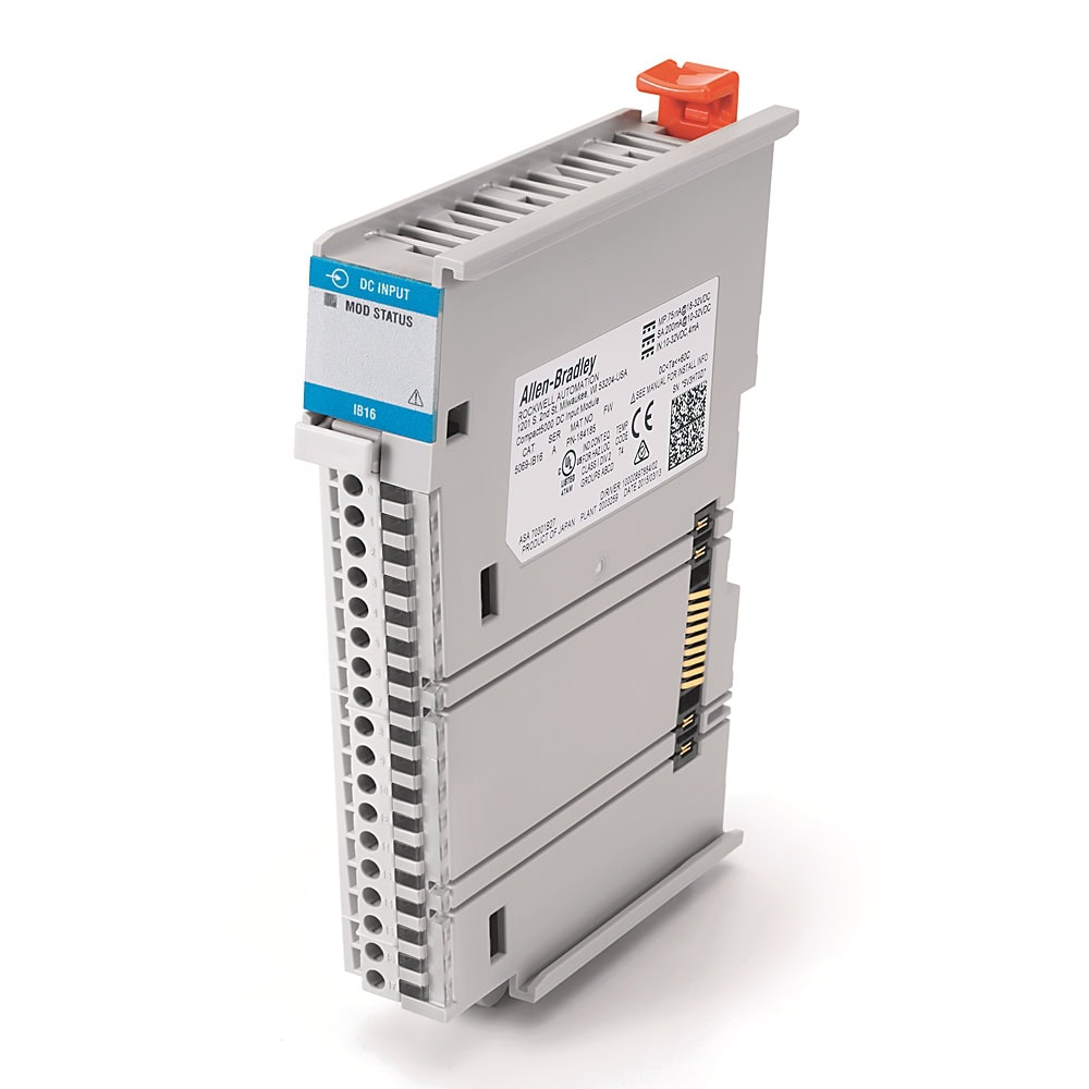
5069-IB16: Digital Input Wiring & Ladder Logic
Sink input wiring for proximity sensors, limit switches, and pushbuttons. Studio 5000 configuration, XIC/XIO ladder logic, and diagnostics.
Read guide →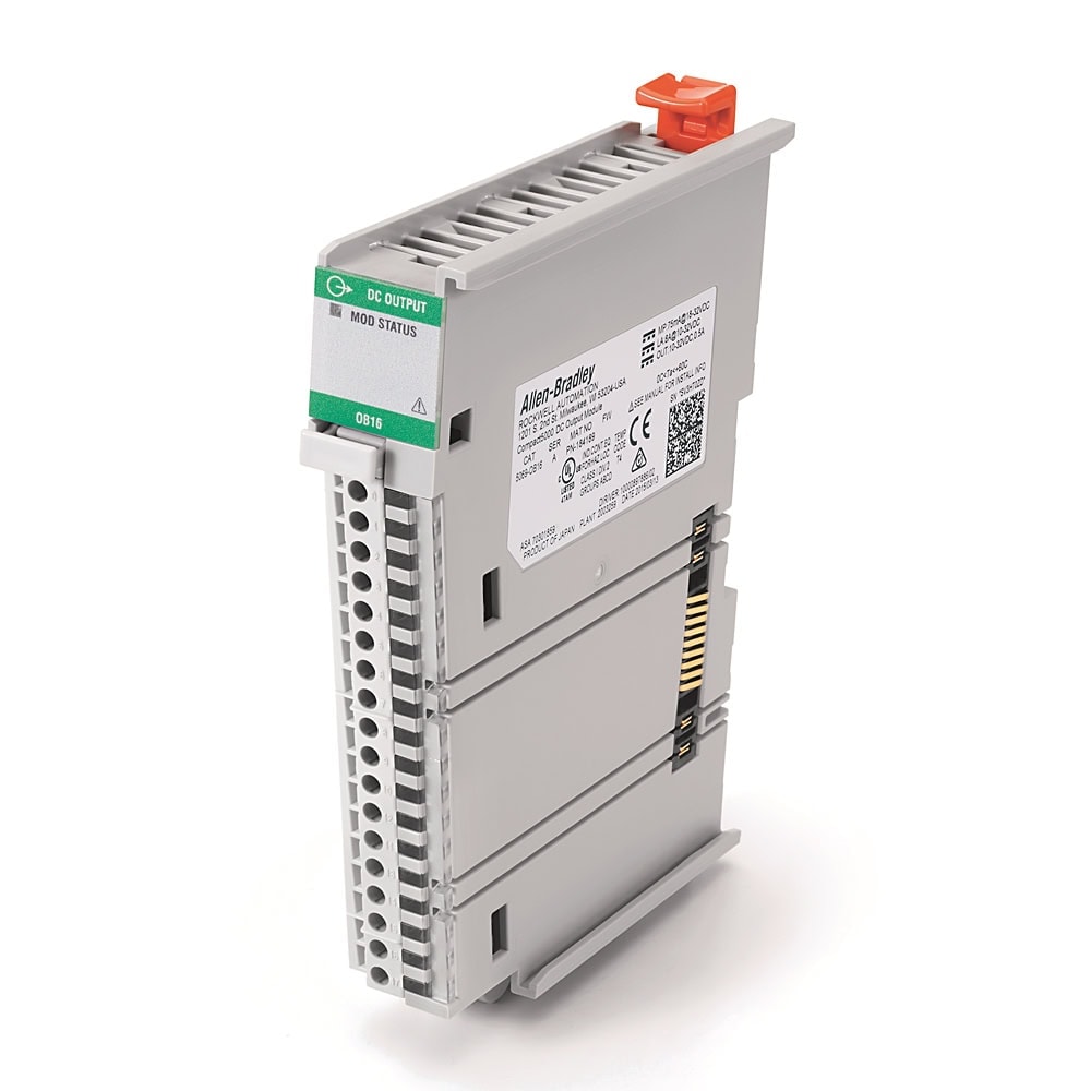
5069-OB16: Digital Output Wiring & Ladder Logic
Source output wiring for solenoids, indicator lights, and motor starters. Fault states, inductive load protection, and OTE/OTL/OTU instructions.
Read guide →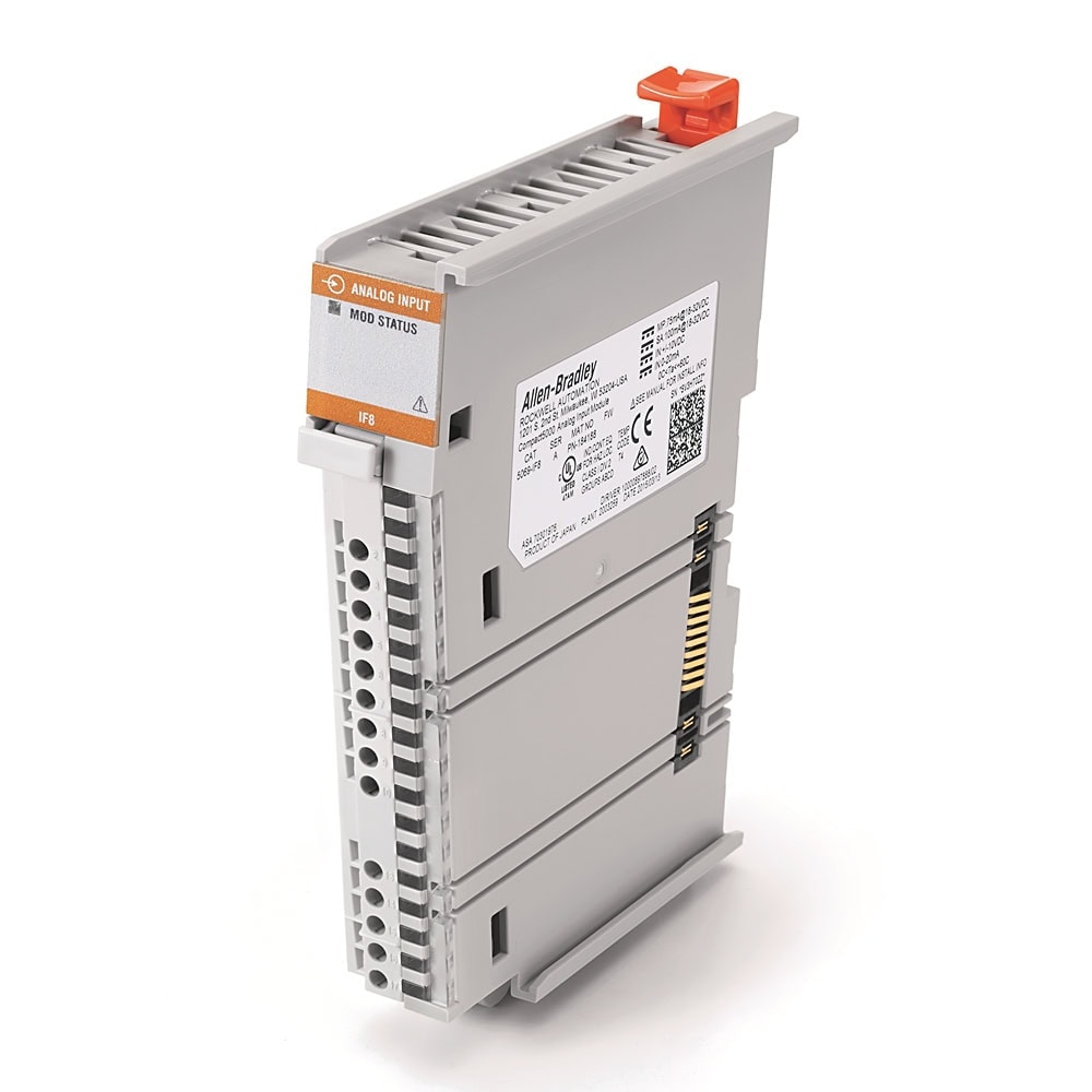
5069-IF8: Analog Input Wiring, Scaling & Config
4-20mA and 0-10V transmitter wiring, SCP scaling to engineering units, per-channel voltage/current config, and calibration best practices.
Read guide →5069-OF8: Analog Output Wiring, Scaling & Control
Controlling valves and VFD speed references with 4-20mA and 0-10V outputs. SCP scaling, fault state config, and a PowerFlex 525 integration example.
Read guide →5069-IY4: RTD, Thermocouple & Temperature Input
Differential 4-channel universal input: current, voltage, RTD (PT100/PT1000/Cu/Ni), and thermocouple (Type K, J, T, E, and more). Cold junction compensation, wiring, and configuration.
Read guide →Analog Signal Types: 4-20mA, 0-10V, RTD & Thermocouple
Understand the differences between 4-20mA, 0-20mA, 0-10V, ±10V, RTD, and thermocouple signals. Covers use cases, noise immunity, wiring best practices, and which Allen-Bradley modules support each type.
Read guide →RTD vs. Thermocouple: Types, Accuracy & Sensor Selection
Deep-dive comparison of RTD and thermocouple sensors. Covers all Pt100/Ni/Cu RTD types, all standard thermocouple types (J, K, T, E, N, R, S, B, C), wiring configurations, accuracy classes, and Allen-Bradley module pairing.
Read guide →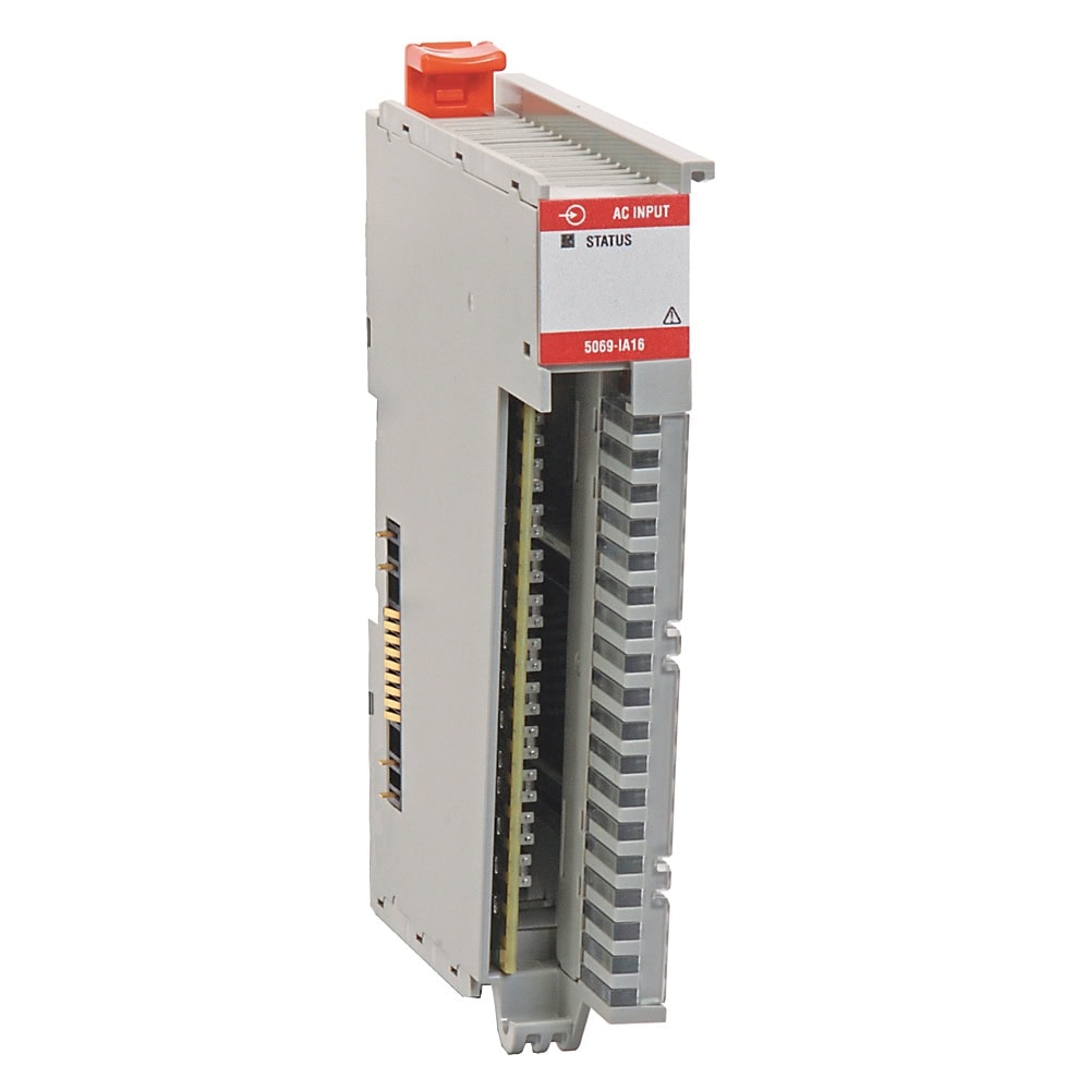
5069-IA16: AC Input Wiring, Config & Ladder Logic
16-channel 120/240V AC digital input: AC field wiring for float switches, pressure switches, and AC sensors. Studio 5000 config, ladder logic, and diagnostics.
Read guide →5069-RTB: Terminal Block Selection, Installation & Wiring
Complete guide to 5069 RTBs — selection table for every Compact 5000 module, spring vs. screw comparison, specs, installation, and wiring best practices.
Read guide →5069-AENTR: EtherNet/IP Adapter Setup & Configuration
Complete guide to the Compact 5000 EtherNet/IP adapter — installation, power wiring, IP setup via rotary switches, Studio 5000 remote I/O configuration, and LED troubleshooting.
Read guide →E-Stop Safety Circuit: GuardLogix 5380 Wiring & Configuration
Design a dual-channel E-Stop circuit with Compact GuardLogix 5380, 5069-IB8S safety input, and 5069-OBV8S safety output. Covers SIL/PL ratings, test outputs, wiring, Studio 5000 safety logic, and system reaction time.
Read guide →5069-IB32: Installation, Wiring & Configuration
Setup guide for the 32-channel 24V DC sinking digital input module: hardware install, dual-RTB field wiring, Group A/B configuration, and programming.
Read guide →1492 IFM Modules & Pre-Wired Cables
The Bulletin 1492 wiring system: interface modules (IFMs), pre-wired/pre-tested 1492-CAB cables, and feed-through terminal blocks — catalog decode, selection, and wiring.
Read guide →Distributed I/O
POINT I/O 17341734-IB8: Wiring, Configuration & Ladder Logic
8-channel 24VDC sinking digital input: terminal wiring for sensors and switches, Studio 5000 configuration with input filter settings, ladder logic examples, and LED diagnostics.
Read guide →1734-OB8: POINT I/O Digital Output Wiring & Config
8-channel 24VDC sourcing output for distributed I/O: load wiring, inductive suppression, fault/program mode configuration, and output control with OTE/OTL/OTU.
Read guide →1734-TB Terminal Bases: Selection, Wiring & Power Distribution
Complete guide to POINT I/O terminal bases — TB vs TB3, screw vs spring, one-piece vs two-piece, TBCJC for thermocouples. Module compatibility table, wiring strip lengths, and POINTBus power budgeting.
Read guide →1734 POINT I/O Power & Wiring: Adapters, Expansion Power & FPD
How to size power for a POINT I/O rack. Covers adapters (AENT/AENTR), expansion power supplies (EP24DC/EPAC), field power distributors (FPD), POINTBus current budgets, and system design examples.
Read guide →Industrial Networking
Stratix 2000HMI & Operator Terminals
PanelView Plus 7PanelView Plus 7: Installation, Config & Application Transfer
Panel cutout mounting, 24VDC power wiring, Ethernet/DLR connection, IP setup, FactoryTalk View ME application loading, LED diagnostics, and maintenance mode recovery.
Read guide →2711P-T10C22D9P: PanelView Plus 7 Performance 10" Setup
Allen-Bradley 10.4" SVGA Performance terminal — catalog breakdown, 8-lever panel mounting, DC power wiring, EtherNet/IP setup, FactoryTalk View ME runtime deployment, and Series A/B differences.
Read guide →Siemens Automation
ET 200SP & SINAMICSET 200SP System Guide: BaseUnits, Modules & ET 200S Migration
Complete system guide for Siemens ET 200SP distributed I/O. Covers interface modules, BaseUnit selection, I/O modules, voltage groups, PROFINET setup, and migration from the older ET 200S platform.
Read guide →IM 151-3 PN HF: ET 200S System Architecture & Migration
Deep-dive on the high-feature PROFINET interface module for the legacy ET 200S — HF vs ST vs FO, advanced features (shared device, MRP, IRT), diagnostics, and migration path to ET 200SP.
Read guide →TP900 Comfort: 9" Panel-Mount HMI Setup & PROFINET Config
Siemens TP900 Comfort Panel — 9" widescreen touch HMI with PROFINET/PROFIBUS, panel cutout, IP65 mounting, TIA Portal WinCC Comfort project deployment, and Comfort family comparison.
Read guide →ET 200SP DI 16x24VDC: Installation, Wiring & TIA Portal
Siemens 16-channel 24VDC sink digital input: BaseUnit assembly, P-reading wiring, TIA Portal setup, input delay parameters, wire-break diagnostics, and LED troubleshooting.
Read guide →SINAMICS G120 CU240E-2: Installation, Wiring & Commissioning
Siemens G120 control unit: Power Module assembly, terminal wiring, PROFINET setup, BOP-2 basic commissioning, motor parameters, and fault diagnostics.
Read guide →SINAMICS G120 PM240-2: Power Module Installation & Wiring
Siemens G120 power module (0.75 kW / 1 HP): wall mounting, shield plates, line and motor terminal wiring, braking resistor connection, and full technical specifications.
Read guide →SCALANCE X208 & X216: Industrial Ethernet Switch Guide
Specs, installation, PROFINET vs EtherNet/IP variants, LED diagnostics, and comparison with Allen-Bradley Stratix 2000 for the Siemens SCALANCE XB-200 family.
Read guide →Technical Articles
Fundamentals
Understanding PLCs: How They Work and Why They Matter
An introduction to Programmable Logic Controllers — what they are, how they work, and why they are integral to modern industrial automation and control systems.
Read guide →
PLC Sensor Calibration & Scaling with Example
How to accurately scale 4–20 mA and 0–10 VDC analog sensor inputs in a PLC, with a worked example for real-world calibration.
Read guide →
Create an SD Card Image for CompactLogix Backup & Restore
How to create a backup image on a 1784-SD1 SD card with any CompactLogix processor — essential knowledge for disaster recovery and program management.
Read guide →
How Do I Become an Automation or Controls Engineer?
An overview of the education, skills, certifications, and career path for becoming an industrial automation or controls engineer.
Read guide →2711P-T10C22D9P: PanelView Plus 7 Performance 10" Setup & Configuration
Install + commissioning guide for the Allen-Bradley 2711P-T10C22D9P 10.4" SVGA PanelView Plus 7 Performance terminal. Hardware, panel cutout, DC power wiring, EtherNet/IP setup, FactoryTalk View ME runtime deployment, and Series A/B differences.
Read guide →Siemens TP900 Comfort: 9" Panel-Mount HMI Setup & PROFINET Configuration
Complete guide to the Siemens TP900 Comfort Panel (6AV2124-0JC01-0AX0). 9" widescreen touch HMI with PROFINET/PROFIBUS, panel cutout, IP65 mounting, TIA Portal WinCC Comfort project deployment, and Comfort family comparison.
Read guide →IM 151-3 PN HF: ET 200S System Architecture & ET 200SP Migration
Deep-dive guide for the Siemens IM 151-3 PN HF interface module — ET 200S system architecture, HF vs ST vs FO comparison, advanced PROFINET features (shared device, MRP, IRT), diagnostics, and migration path to ET 200SP.
Read guide →PLC-5 to ControlLogix Migration: Hardware, I/O, Wiring, and Software
Comprehensive migration guide from Allen-Bradley PLC-5 (Bulletin 1785) to ControlLogix (Bulletin 1756). Four migration paths — full replacement, 1492-AIFM swing-arm wiring conversion, 1756-DHRIO remote I/O bridge, and EtherNet/IP via 1756-AENT. Hardware equivalents, RSLogix 5 → Studio 5000 conversion, sample BOM.
Read guide →SLC 500 to ControlLogix Migration: I/O, Wiring, and Strategy
Comprehensive migration guide from Allen-Bradley SLC 500 (Bulletin 1746/1747) to ControlLogix. Covers all four migration paths with the marquee 1747-AENTR adapter approach that preserves the SLC chassis as remote I/O. Hardware equivalents, RSLogix 500 → Studio 5000 conversion, sample BOM.
Read guide →Coming Soon
PowerFlex 525 for Conveyor Applications
In progressPowerFlex 525 Fault Codes & Troubleshooting
In progressAdding a PanelView HMI to a 5069 System
In progressConnecting a PowerFlex 525 to a 5069 PLC
In progressS7-1200 First Setup with TIA Portal
In progressCan't find what you're looking for?
PLC Exchange[email protected]
980-202-0882
Our team answers technical questions on parts we sell.